Parasitic Extraction
This page shows how to get every element of a transformer's equivalent circuit from TRAFOLO: winding resistances, magnetizing and leakage inductance, core-loss resistance, and interwinding and self-capacitance. Each element comes from its own run; the table below names the run and where you read the result.
Equivalent circuit and where each element comes from
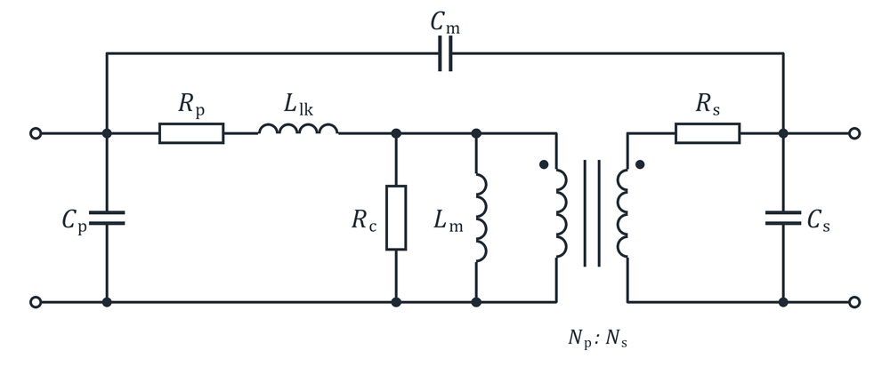
| Element | What it represents | Run in TRAFOLO | Where to read it |
|---|---|---|---|
| Rp, Rs | Winding resistance: DC plus skin and proximity loss | Harmonic, or Inductance for a sweep over frequency | Rdc, Rac Loss (Inductance view); Primary Loss [W], Secondary Loss [W] (Summary) |
| Llk | Leakage inductance: flux that does not link both windings | Inductance, secondary Urms [V] = 0 (shorted) | Circuit Inductance, Energy Inductance (Inductance view) |
| Lm | Magnetizing inductance | Inductance, secondary Irms [A] = 0 (open) | Circuit Inductance, Energy Inductance (Inductance view) |
| Rc | Core loss as a parallel resistance | Harmonic at the operating point, or the magnetizing Inductance run | Core Loss [W] (Summary); Rc ≈ Urms²/Pcore |
| Cm | Interwinding capacitance | Harmonic or Transient with Capacitance | Capacitance Matrix (Summary): line Primary-Secondary of the matrix file |
| Cp, Cs | Self-capacitance of a winding | Inductance, Full, Without Circuits (one solid conductor); or the capacitance matrix (separate turns) | Capacitance [pF] (Inductance view); Capacitance netlist (Export Results) |
Definitions of every result: Results, section Inductance, Rac and Q.
Broadband model of an inductor. For a single-winding inductor, High Frequency Mode (Preset on Setup) sweeps the impedance over frequency and fits a circuit to it. Export Results › CIRCUIT MODEL saves it as Touchstone (.s2p) or SPICE subcircuit (.lib): an RL ladder for Rdc, the inductance and the rise of Rac with frequency, with a capacitance across the terminals for the self-resonance.
Winding resistance: Rdc and Rac
Skin and proximity effects raise the AC resistance of a winding above its DC resistance as the frequency rises. The rise is largest near air gaps, where the fringing field crosses the winding and crowds the current.
| Result | Definition | What it includes | Where |
|---|---|---|---|
| Rdc | DC resistance from the conductor geometry and the conductivity at the Steady-State Temperature (Heat tab, 20 °C (default); Predicted Steady-State Temperature with steady-state heat transfer on) | DC only | Component Values (every winding, coil group and turn), Inductance view; R DC coil [Ω] in Summary |
| Rac Loss | Pwinding/Irms² | The winding only: DC, skin and proximity loss | Inductance view (primary) |
| Rac Circuit | Re(V/I) at the winding's source | Every loss inside the field solution: winding, eddy currents in the core and other parts, a complex-permeability core; with a loaded secondary, also the power passed to it | Component Values, Inductance view; R AC source [Ω] in Summary |
| Proximity Factors | Rac/Rdc per Stranded & Litz group and frequency | Dowell's Equation or the fixed Proximity Factor; none for Homogenization | Results › Proximity Factors |
Use the winding loss for Rp and Rs, not Rac Circuit. Rac Circuit also holds the eddy-current loss of the core and, for a coupled winding, the power passed to the other winding. For the secondary, take Rs = Secondary Loss [W]/Irms², with Irms of the secondary from Component Values.
How the Wire Type sets Rac
| Wire Type (Coil) | Where the skin and proximity loss come from |
|---|---|
| Stranded & Litz | The method chosen in Configure Wire: Dowell's Equation, Homogenization or Rac/Rdc coefficient (a fixed Proximity Factor). See Homogenization of Litz and Stranded Windings. |
| Foil, Flat wire | The field solution of the sheet model: the current changes along the foil height, not across its thickness. |
| Massive (solid) | The field solution. Resolve the skin depth with Boundary Layers on the Mesh tab (copper at 20 °C: 0.21 mm at 100 kHz, 0.065 mm at 1 MHz), or use Impedance boundary in Inductance runs. |
Rac equals Rdc by default. A new coil group, also one created in the CAD Editor, starts as Stranded & Litz with Rac/Rdc coefficient and Proximity Factor 1 (default): its Rac Loss equals Rdc at every frequency. Choose Dowell's Equation or Homogenization in Configure Wire, or Massive (solid), before you read Rac.
Rac over frequency or current: run an Inductance sweep with SWEEP BY Frequency or Excitation (next section), or a Harmonic run with several frequencies, which lists the losses per frequency in the Summary.
Magnetizing and leakage inductance
The magnetizing inductance Lm is set by the primary turns, the core material and the air gap; it falls as the core approaches saturation. The leakage inductance Llk comes from the flux that does not link both windings; the arrangement and interleaving of the windings set it. An Inductance run gives either one, depending on how the secondary is driven.
- On Setup, under ELECTROMAGNETICS, select Inductance. Heat transfer stays off in Inductance runs.
-
On ElMag, tick Secondary Winding and set its Excitation (1): Urms [V] for the leakage inductance, Irms [A] for the magnetizing inductance.
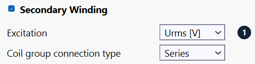
ElMag › Secondary Winding: Excitation (1) on Urms [V], for the leakage inductance. -
On Waveform, under SWEEP BY, select Excitation or Frequency, set Fixed Frequency (or Fixed Irms / Fixed Urms for a frequency sweep) and type the primary values of the sweep. The secondary value is 0 and read only: 0 V shorts the secondary, 0 A leaves it open.
- Mesh and solve the model as usual.
- On Results › Inductance, read Circuit Inductance and Energy Inductance for each sweep point.
Details of the sweep: Inductance (frequency and excitation sweeps).
Video (3 min): the leakage inductance of a transformer with the secondary shorted (recorded in an earlier TRAFOLO version).
What the primary sees. With the secondary shorted, Circuit Inductance is Llk of the circuit above, the leakage of both windings referred to the primary (for Lm ≫ Llk), and Rac Circuit is the short-circuit resistance Rp + Rs·(Np/Ns)² plus the eddy-current loss of the core. With the secondary open, Circuit Inductance is Llk + Lm ≈ Lm.
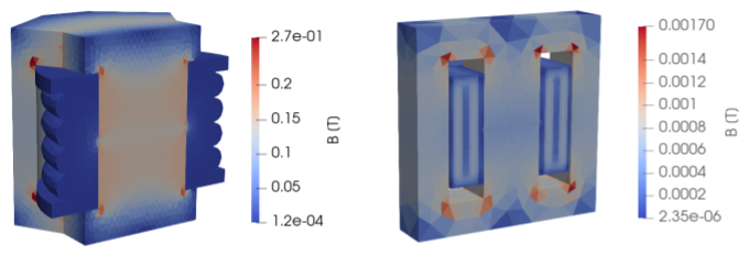
Circuit or Energy Inductance
Circuit Inductance = Im(V/I)/ω is the inductance at the terminals. Energy Inductance = 2Wm/I², with Wm the magnetic energy of the whole model, from the energy density um = ½B·H. Both agree within a few percent in a converged solution; a larger difference points to the mesh or to convergence. The energy form holds for a linear material only: with a B-H curve the stored energy is ∫H·dB, and 2Wm/I² differs from the inductance at the terminals. Use Circuit Inductance for a saturating core.
Coupling factor from the two runs above: k = √(1 − Lsc/Loc), with Lsc the primary Circuit Inductance with the secondary shorted and Loc with it open. The four-run method of IEC 61007: Coupling Factor.
Core-loss resistance
TRAFOLO computes the core loss from the core-loss model of the material after the field solution (Core Properties and Models) and reports it as Core Loss [W] in the Summary. For the equivalent circuit, Rc ≈ Urms²/Pcore, with Urms the primary voltage from Component Values. Rc changes with flux density and frequency: take it from a run at the operating point. The loss of a complex-permeability core is part of the field solution and also appears in Rac Circuit.
Interwinding capacitance and the capacitance matrix
The interwinding capacitance Cm couples the primary to the secondary. It carries common-mode current from the switching edges, i = C·dv/dt: 37.3 pF and a 10 V/ns edge drive 0.37 A. The winding arrangement, the distance between the windings and the permittivity of the insulation set it.
- Model the insulation between the conductors as bodies (bobbin, tape, board, potting) and give each material its Relative Permittivity on Materials. Air has a Relative Permittivity of 1.
-
On Setup, under ELECTROMAGNETICS, select Harmonic or Transient and tick Capacitance (2).

Setup: Capacitance (2) is available with Harmonic and Transient. -
On Mesh, refine the thin insulation between turns and windings: select the bobbin or insulation body and set a smaller All Max Element Edge Size [mm].
- Mesh and solve the model as usual. TRAFOLO adds one electrostatic solve per electrode, so the run time grows with the number of separate turns.
-
On Results › Summary, click Capacitance Matrix (3) in the Capacitance box. TRAFOLO opens the full matrix, results/capacitance_matrix.csv, in the program that opens .csv files. Its last line, Primary-Secondary, is the interwinding capacitance: 3.732e-11 F, 37.3 pF, for the Flyback Transformer template.
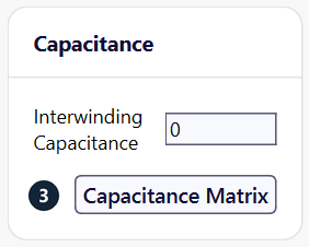
Summary of the Flyback Transformer template: Capacitance Matrix (3). TRAFOLO 1.64 shows 0 in the Interwinding Capacitance box for any value below 1 nF: it rounds the value in farads to 9 decimals. Read the interwinding capacitance from the Primary-Secondary line of the matrix file.
-
To use the matrix in a circuit simulator, click Export Results › Capacitance netlist and save the SPICE file (.cir).
Conductors that touch. When two conductors share a face in the geometry, with no insulation between them, TRAFOLO shows Capacitance Matrix Warning: the terms between them are not meaningful. Add the insulation layer or a gap in the CAD and solve again.
How TRAFOLO computes the matrix
- Electrodes: every coil body, and every other body whose material has an Electric Conductivity above 0, such as a ferrite core. Conductive bodies that touch form one electrode, except that a coil body is never merged with a core, another part or another coil group. All other bodies are dielectrics with their Relative Permittivity.
- One solve per electrode: that electrode at 1 V, all other electrodes and the outer boundary of the air box at 0 V. The charges induced on the others give one row of the matrix.
- Off-diagonal Cij: the mutual capacitance between electrodes i and j. Diagonal Cii: the capacitance of electrode i to the outer boundary of the air box.
- Interwinding Capacitance: the sum of all Cij between a primary and a secondary electrode, each winding taken as one equipotential. The matrix file ends with this sum (Primary-Secondary, in F) and, with a second secondary, Primary-Secondary2 and Secondary-Secondary2.
- Symmetric models: TRAFOLO doubles every entry, so all values are for the whole component.
Capacitance to the air box. The diagonal terms grow as the air box shrinks. Treat them as an upper bound unless the air-box surface stands for a real ground, such as a chassis or a screen.
Example: Flyback Transformer template
The Flyback Transformer template (RM8 core, Ferroxcube 3C97, half model) has six electrodes: the core, the 24-turn primary drawn as one homogenized body, and the four secondary turns, one body each.
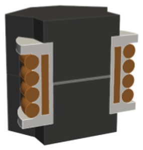
| pF | Group1core (core) | Group1coil1 (primary) | Group2coil1 (secondary) | Group2coil2 (secondary) | Group2coil3 (secondary) | Group2coil4 (secondary) |
|---|---|---|---|---|---|---|
| Group1core | 1.73 | 19.95 | 3.14 | 1.30 | 1.28 | 3.16 |
| Group1coil1 | 19.95 | 0.06 | 9.80 | 9.11 | 8.94 | 9.47 |
| Group2coil1 | 3.14 | 9.80 | −0.07 | 8.35 | 0.01 | 0.01 |
| Group2coil2 | 1.30 | 9.11 | 8.35 | 0.04 | 8.57 | 0.01 |
| Group2coil3 | 1.28 | 8.94 | 0.01 | 8.57 | −0.02 | 8.55 |
| Group2coil4 | 3.16 | 9.47 | 0.01 | 0.01 | 8.55 | 0.06 |
- Interwinding capacitance, line Primary-Secondary of the file: 9.80 + 9.11 + 8.94 + 9.47 = 37.3 pF, the primary row against the four secondary turns.
- Neighbouring secondary turns: 8.35 to 8.57 pF. Turns that are not neighbours: about 0.01 pF, shielded by the turns between them.
- The primary is one electrode, so the matrix holds no turn-to-turn capacitance of the primary.
- Entries below about 0.1 pF, including the two negative diagonal entries, are numerical noise. The netlist export leaves out entries that are not positive.
Coupling through a floating core. Interwinding Capacitance sums the direct terms only. With a floating core, the path primary–core–secondary adds 19.95 pF and 8.87 pF in series, about 6 pF here. The netlist keeps the core as its own node, so a circuit simulation includes this path.
Capacitance netlist
Export Results › Capacitance netlist writes two SPICE subcircuits. trafolo_capacitance has one capacitor per matrix entry and one pin per electrode. trafolo_capacitance_lumped has each winding as one node, for common-mode and interwinding studies. Pin GNDREF is the air-box surface: tie it to ground only for a grounded enclosure. The file header lists the node map and, for runs with circuits, the order of the turns along each winding.
Self-capacitance of a winding
The self-capacitance Cp or Cs lumps the capacitance between the turns and layers of one winding and to the parts around it. With the winding inductance it sets the self-resonant frequency. It depends on the winding geometry, the turn order and the permittivity around the turns, and hardly on frequency.
Winding made of one solid conductor
For a winding that is one continuous solid body, such as a planar or PCB winding imported from CAD, TRAFOLO computes the capacitance from the electric field energy of an Inductance run without circuits: We = ½∫ε|E|² dV and C = 2We/V², with V the peak voltage across the winding terminals.
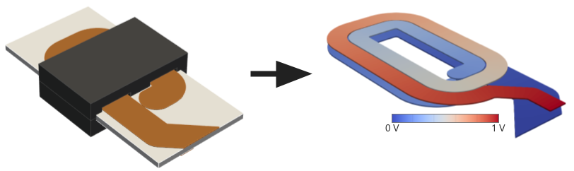
- On Setup, under DOMAIN TYPE, select Full.
- Under ELECTROMAGNETICS, select Inductance and tick Without Circuits.
- On ElMag, set Coil group connection type to Series and the coil group's Connection to Series, as in the Planar Inductor template. The Excitation is fixed to Urms [V].
- On Waveform, under SWEEP BY, select Frequency, set Fixed Urms to the voltage, 1 V in the template, and type the frequencies.
- Mesh and solve the model as usual.
-
On Results › Inductance, read Capacitance [pF] (4).
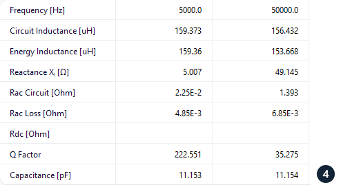
Planar Inductor at 1 V: Capacitance (4) is 11.2 pF at both 5 and 50 kHz.
Without Circuits limits: Full domain, Inductance, 1 phase, one source and voltage excitation only. Rdc stays empty unless the sweep includes 0 Hz. See Without circuits.
Winding of separate turns
For a winding drawn as separate turns that do not touch, run Capacitance as for the interwinding capacitance: the matrix holds every turn-to-turn capacitance. The self-capacitance follows from these values and the voltage distribution along the winding, so TRAFOLO does not reduce it to one number. Export the Capacitance netlist and, in your circuit simulator, connect the turn nodes in winding order through the inductance and resistance of each turn.
A block is one electrode. A winding drawn as one body, such as a Stranded & Litz or Foil block with many turns, is one electrode: TRAFOLO does not compute its turn-to-turn capacitance. Turns of one coil group that touch also merge into one electrode. Draw the turns as separate bodies with insulation or a gap between them to get it.
Related
- Results: every result and its definition, Export Results
- Setup: Capacitance, Without Circuits, High Frequency Mode
- Inductance (frequency and excitation sweeps) and Coupling Factor
- Templates: Flyback Transformer (interwinding capacitance), Planar Inductor (self-capacitance)
Further reading
- Uncovering inductor self-capacitance: measuring with a VNA (TRAFOLO on LinkedIn)
- Domain size: why should(n't) you make a large airbox and extend terminals (TRAFOLO on LinkedIn)
- J. Biela, J. W. Kolar, Using transformer parasitics for resonant converters: a review of the calculation of the stray capacitance of transformers, IEEE IAS Annual Meeting, 2005.