TEAM Problem 7: Eddy Currents in a Plate Compared with Measurements
TRAFOLO computes the eddy currents of TEAM Problem 7, the Compumag benchmark of an aluminium plate with a hole under a coil, within 1.6 to 6.5 % of the measurement on 14 of its 16 measured curves, at 50 and 200 Hz.
- Result: Bz above the plate 2.5 to 5.4 %, Jy on both plate faces 1.6 to 6.5 % (mean difference in % of each curve's largest measured value). Two curves are left out and three printing errors of the published tables are corrected, see Reference data.
- Source: TEAM Problem 7 description, Compumag Society; K. Fujiwara, T. Nakata, "Results for benchmark problem 7 (asymmetrical conductor with a hole)", COMPEL 9(3), 1990, pp. 137–154, doi:10.1108/eb010071.
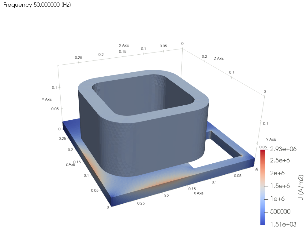
Case
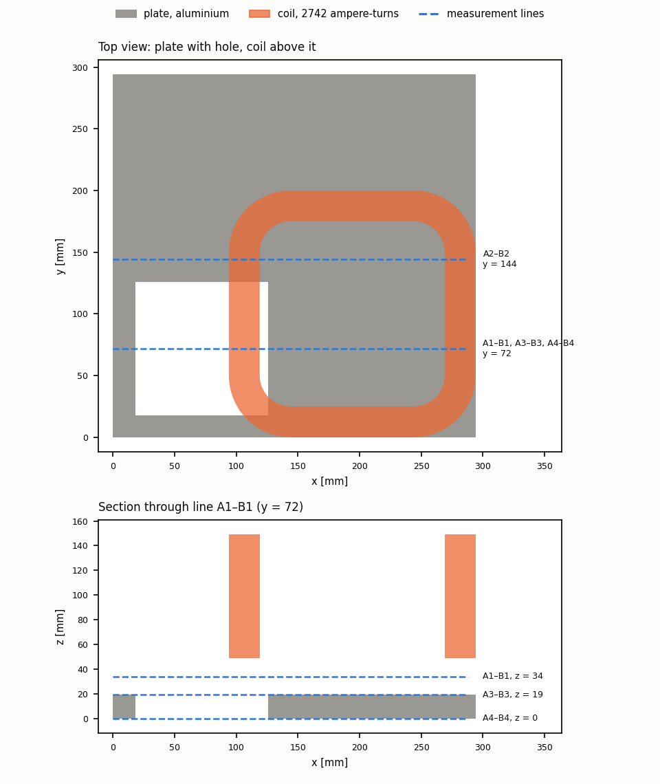
| Part | Material in the model | Size [mm] | Position [mm] |
|---|---|---|---|
| Plate | Aluminum: σ = 3.526 × 10⁷ S/m, μr = 1, temperature coefficient 0 | 294 × 294 × 19 | x, y = 0–294, z = 0–19 |
| Hole, through the plate | – | 108 × 108 | x, y = 18–126 |
| Coil | Copper, Stranded & Litz | outside 200 × 200 (corner radius 50), inside 150 × 150 (radius 25), 100 high | x = 94–294, y = 0–200, z = 49–149 |
- Excitation: 2742 ampere-turns peak at 50 and 200 Hz. Skin depth in the plate: 12.0 mm at 50 Hz, 6.0 mm at 200 Hz.
- Measured: Bz at z = 34 mm on lines A1–B1 (y = 72 mm) and A2–B2 (y = 144 mm); Jy on the top face (A3–B3, z = 19 mm) and on the bottom face (A4–B4, z = 0) at y = 72 mm. Points every 18 mm from x = 0 to 288 mm, at ωt = 0° and 90°.
- Air box: −500 to 650 mm on every axis.
Reference data
The published tables (problem7.pdf, p. 14) carry three printing errors, corrected here:
- The two Jy tables are printed under swapped headings: table (b) belongs to the top face and table (a) to the bottom face, as the 1990 results paper plots them.
- In all four Jy tables the ωt = 0° and 90° columns are interchanged, with their signs reversed; the 1990 paper's own figures plot the measured points this way.
- On the bottom face at 50 Hz the values belong one measurement position further along the line; printed as they are, they sit one position off the results of all 25 codes of the 1990 benchmark.
Two measured curves are left out: Bz at 200 Hz and ωt = 90° on A1–B1 and A2–B2. This out-of-phase field is at most 5 G. Independent published FEM results agree with TRAFOLO there, and the measured curves would mean that the plate loss hardly grows from 50 to 200 Hz. The corrected values are attached.
Results
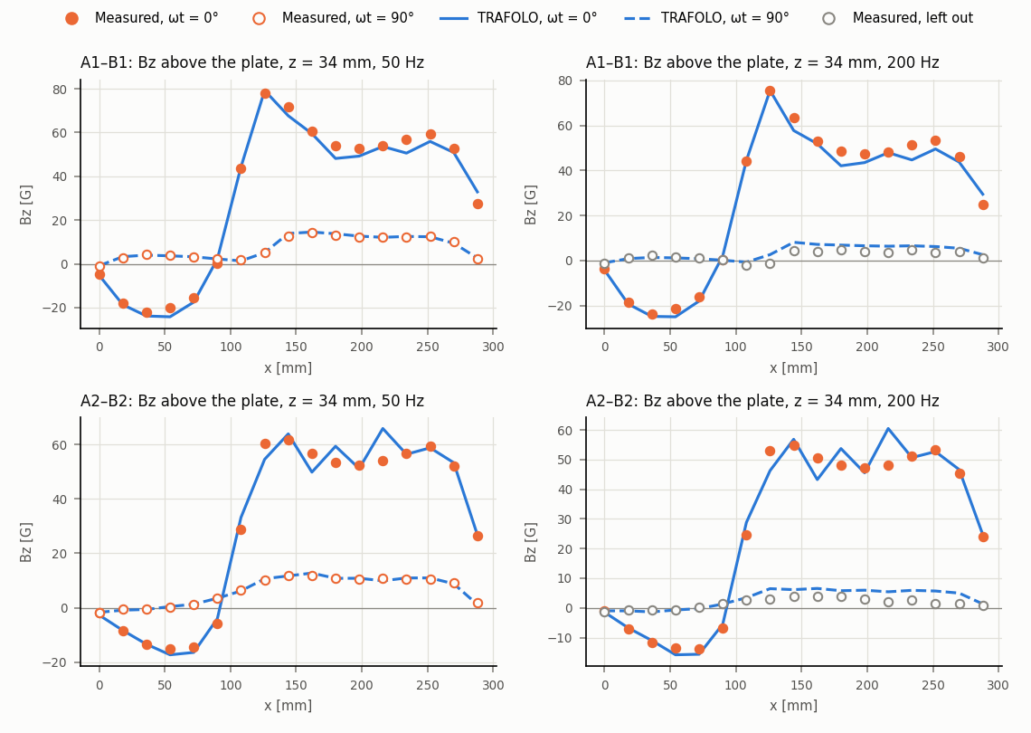
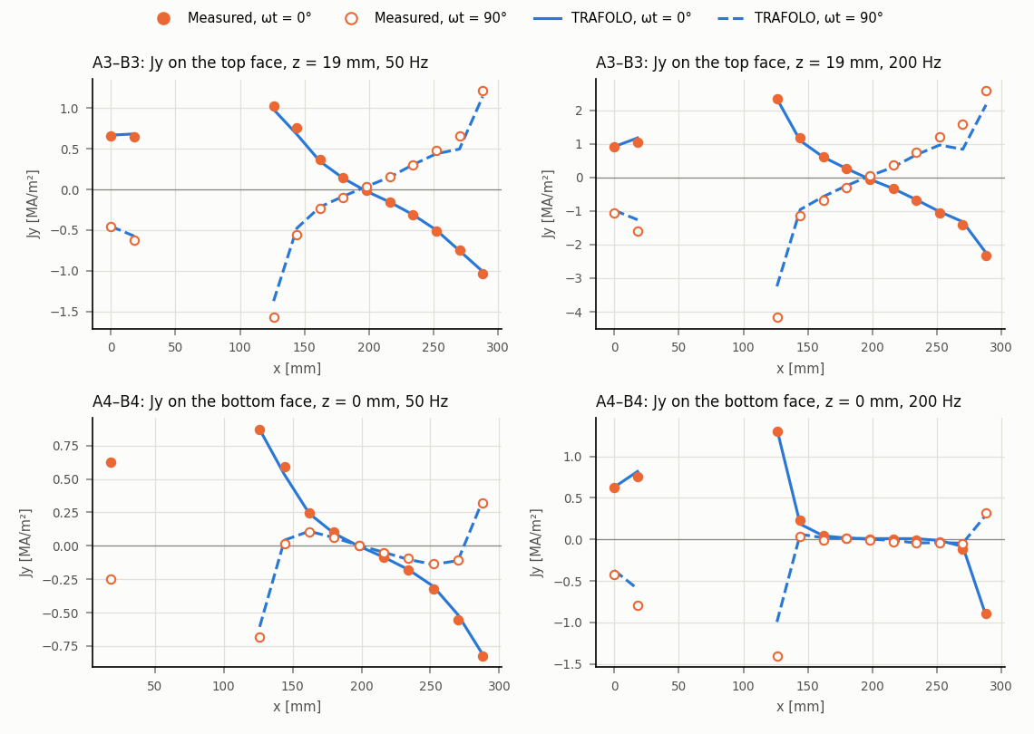
| Mean difference, run R2 [%] | 50 Hz, ωt = 0° | 50 Hz, ωt = 90° | 200 Hz, ωt = 0° | 200 Hz, ωt = 90° |
|---|---|---|---|---|
| Bz above the plate, A1–B1 | 3.3 | 2.5 | 3.5 | left out |
| Bz above the plate, A2–B2 | 4.5 | 2.8 | 5.4 | left out |
| Jy on the top face, A3–B3 | 2.0 | 3.4 | 1.7 | 6.5 |
| Jy on the bottom face, A4–B4 | 1.8 | 3.2 | 1.6 | 4.6 |
Difference: TRAFOLO minus measured, in % of the largest measured value on the same curve, so that values near a zero crossing do not inflate it.
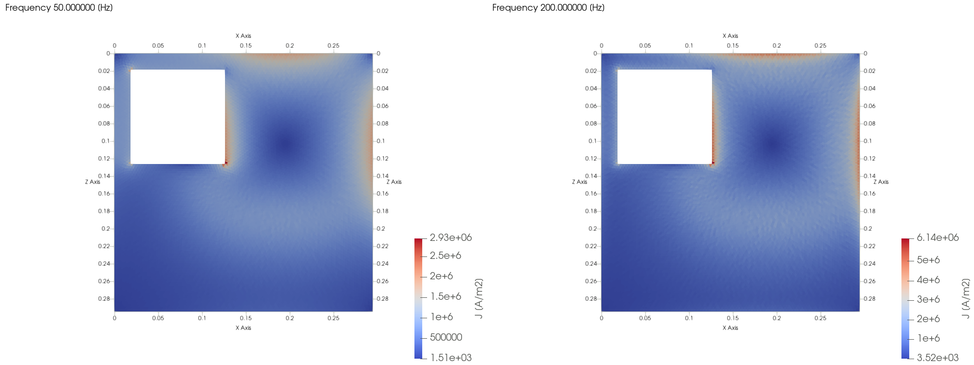
The eddy currents circle under the coil and crowd along the hole edge and the plate edges, where the Jy lines cross them. At 200 Hz they are stronger and kept closer to the surface.
TRAFOLO model
The TEAM7 template that ships with TRAFOLO, with the hole at its published position, in TRAFOLO 1.66.1beta. The template's y axis points up: template (x, y, z) = TEAM (x, z, y).
| Tab | Setting |
|---|---|
| Setup | DOMAIN TYPE Full: the plate has no symmetry plane. ELECTROMAGNETICS Inductance. |
| Other | The plate, imported from TEAM07_plate_template_axes.step (attached). |
| Materials | Plate: Aluminum (σ = 3.526 × 10⁷ S/m, temperature coefficient 0). Coil: Copper. |
| Coil | Stranded & Litz, Turns per solid 2742, Closed coil. |
| ElMag | Coil on the primary, current excitation. |
| Waveform | Inductance Sweep, SWEEP BY Frequency: 50 and 200 Hz, primary 0.70711 A rms. |
| Mesh | Plate Max Element Edge Size 2 mm (a third of the 200 Hz skin depth), coil 4 mm, Growth Rate 0.3; 1 084 071 elements. |
| Solve | 16 cores, Solver Preset Normal: both frequencies in about 20 minutes. |
The fields are read at the measured points: ωt = 0° is the real part of the complex field, ωt = 90° the negative imaginary part. Jy at the hole edges (x = 18 and 126 mm) is read 0.1 mm inside the metal.
Checks
- Mesh: refining the plate from 6 to 3 to 2 mm takes Bz on A1–B1 at 50 Hz from 7.3 to 4.3 to 3.3 %. With the 3 mm plate, 350 000 elements, both frequencies solve in about 4 minutes on 16 cores.
- Air box: doubling it shifts Bz by about 0.5 % on average and by 3 % at most.
All runs
| Run | Plate / coil mesh [mm] | Growth Rate | Air box [mm] | Elements | Mesh / solve time [s] | Bz A1–B1 mean, 50 / 200 Hz [%] | Note |
|---|---|---|---|---|---|---|---|
| R0 | 6 / 6.25 | 0.5 | −500…650 | 134 228 | 78 / 264 | 7.3 / 7.8 | First run |
| R1 | 3 / 6.25 | 0.3 | −500…650 | 346 418 | 175 / 260 | 4.3 / 4.3 | Mesh check |
| R2 | 2 / 4 | 0.3 | −500…650 | 1 084 071 | 534 / 1155 | 3.3 / 3.5 | Reference run |
| R3 | 3 / 6.25 | 0.3 | −1000…1150 | 348 450 | 75 / 180 | 4.1 / 4.4 | Air box doubled |
Each run solves 50 and 200 Hz on 16 cores.
Limits
- Values per element: B and J are constant inside each element, so a single point value moves with the mesh by up to 10 %, while the mean along a line converges.
- Hole edges (x = 18 and 126 mm on the Jy lines) are corners: the values there are read 0.1 mm inside the metal.
- Two curves left out: Bz at 200 Hz and ωt = 90°, see Reference data.
Related
- Other: conductive parts such as this plate, which carry eddy currents
- Inductance (frequency and excitation sweeps)e
- Mesh: element sizes and growth rate