Inductance of a Gapped E-Core Inductor Compared with Measurements
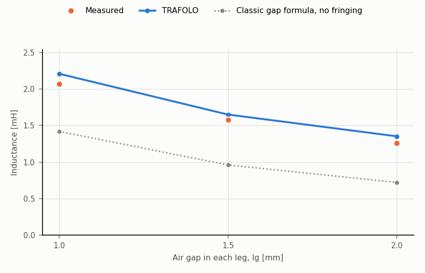
TRAFOLO computes the inductance of a gapped E-core inductor within 5 to 7 % of the measurement, at gaps of 1.0 to 2.0 mm. The classic gap formula, which leaves out the fringing flux, is 31 to 43 % too low.
- Result: 2.21, 1.65 and 1.35 mH against 2.07, 1.58 and 1.26 mH measured, at gaps of 1.0, 1.5 and 2.0 mm.
- Source: J. Mühlethaler, J. W. Kolar, A. Ecklebe, "A Novel Approach for 3D Air Gap Reluctance Calculations", 8th International Conference on Power Electronics – ECCE Asia 2011, pp. 446–452, doi:10.1109/ICPE.2011.5944575.
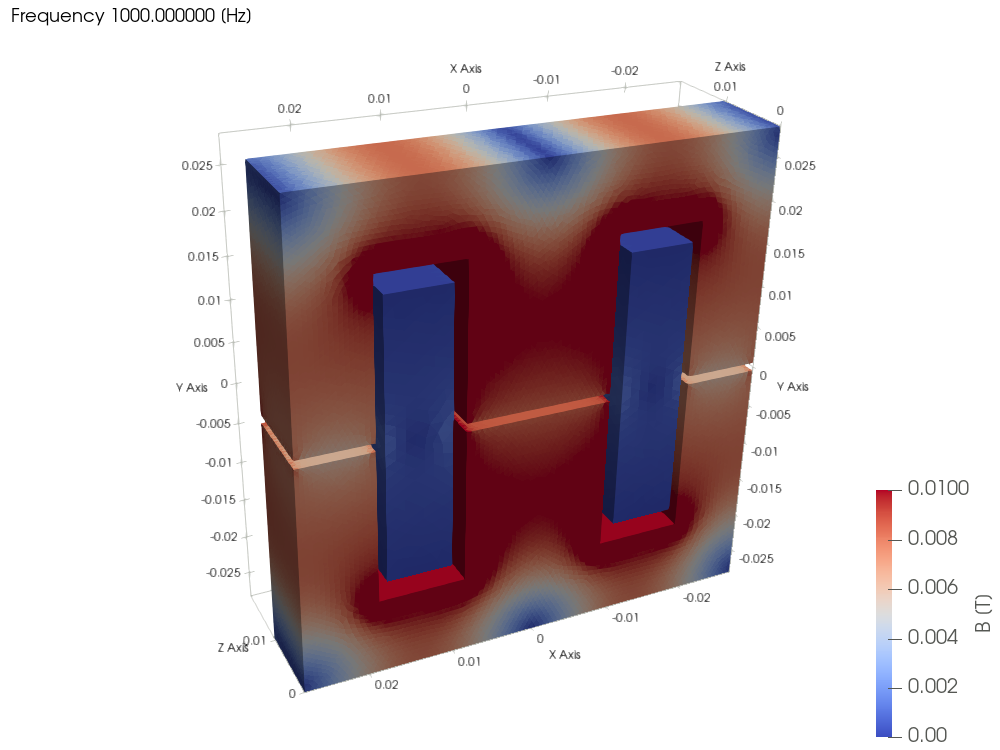
Case
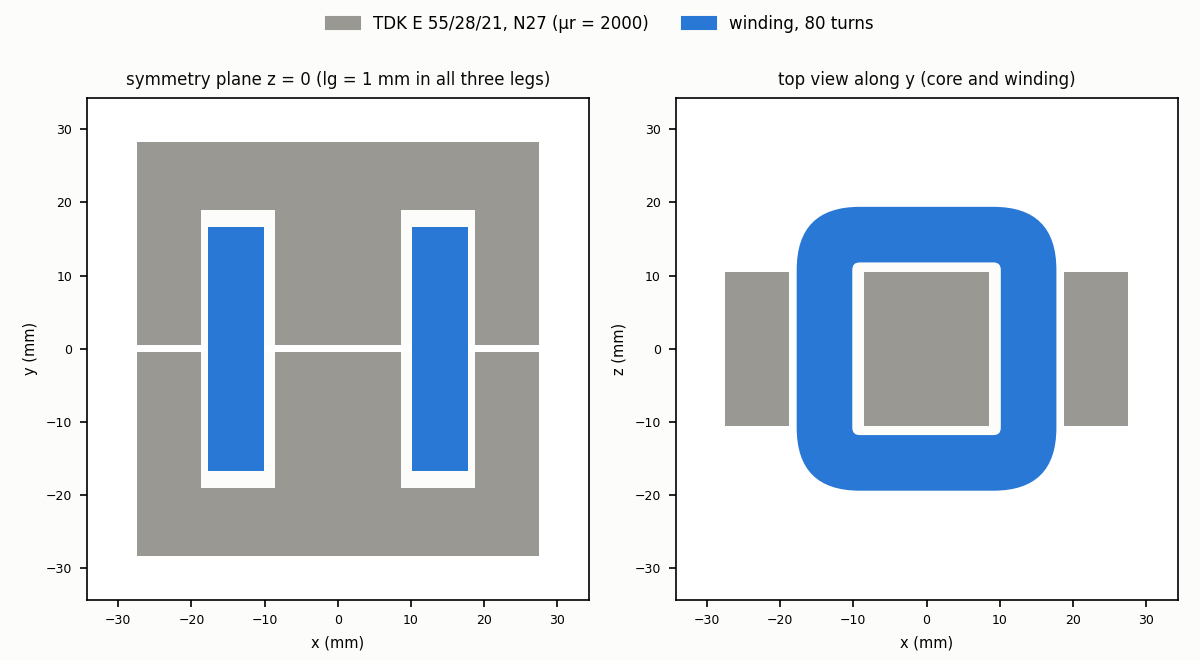
| Part | Material in the model | Size [mm] |
|---|---|---|
| Core, two halves | N27 mur2000: μr = 2000, σ = 0, no core loss | TDK E 55/28/21: 55 × 27.8 × 21 each, centre leg 17.2 × 21 |
| Air gap, in all three legs | Air (any non-magnetic spacer) | lg = 1.0, 1.5, 2.0 |
| Winding | Copper, Stranded & Litz, 80 turns | On the TDK B66252 coil former, centred on the gaps |
- Excitation: 0.1 A rms at 1 and 10 kHz. The model is linear and has no eddy currents, so the inductance depends on neither.
- Measured: one inductance per gap (paper, Table I).
- Air box: automatic, 3 × the part.
Results
| Gap lg [mm] | Measured [mH] | TRAFOLO [mH] | Difference [%] | Classic gap formula [mH] |
|---|---|---|---|---|
| 1.0 | 2.07 | 2.212 | +6.9 | 1.42 |
| 1.5 | 1.58 | 1.652 | +4.6 | 0.96 |
| 2.0 | 1.26 | 1.353 | +7.4 | 0.72 |
TRAFOLO follows the measured fall of the inductance with the gap. The classic formula counts only the gap cross-sections and misses the fringing flux, so it is 31 to 43 % low.
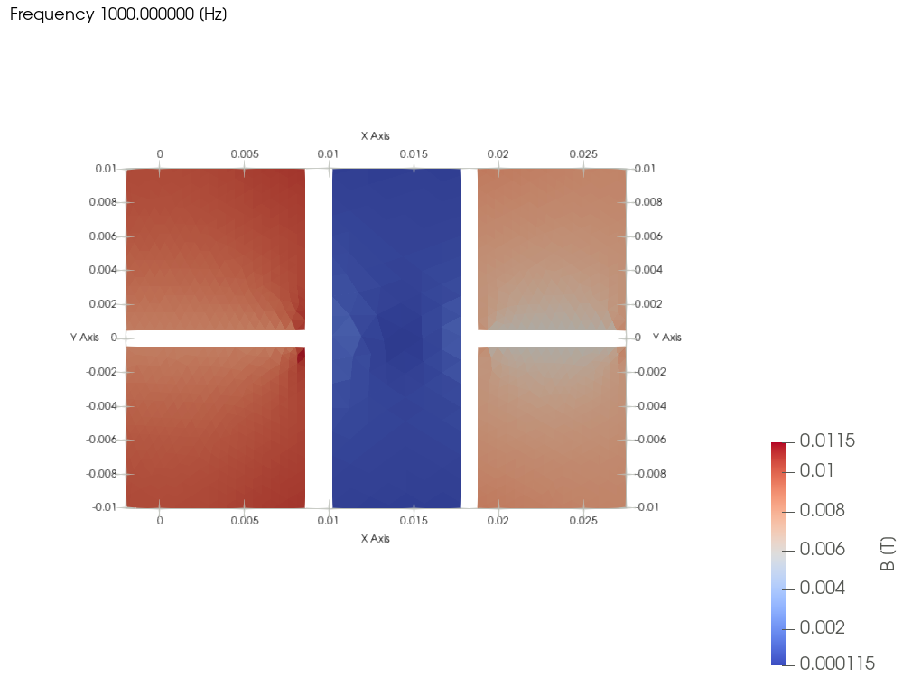
Near the gaps part of the flux leaves the core faces and bypasses the gap through the window and around the outer leg. This fringing widens the effective gap area: the measured inductance is 46 to 75 % above the classic formula, more at larger gaps.
TRAFOLO model
Built from STEP files of the two core halves and the winding (attached), one project per gap, in TRAFOLO 1.66.1beta.
MUH_lg1p0.stepMUH_lg1p5.stepMUH_lg2p0.step
| Tab | Setting |
|---|---|
| Setup | DOMAIN TYPE Symmetric: a half model, cut at the mid-depth plane. ELECTROMAGNETICS Inductance. |
| Geometry | CAD import of the two core halves, lg apart, and the winding, scale mm. The gaps are air. |
| Materials | Cores: N27 mur2000 (μr = 2000, the initial permeability of N27). Winding: Copper. |
| Coil | Stranded & Litz, Turns per solid 80. |
| ElMag | Winding on the primary, current excitation. |
| Waveform | Inductance Sweep, SWEEP BY Frequency: 1 and 10 kHz, 0.1 A rms. |
| Mesh | Max Element Edge Size: cores 1 mm, winding 2 mm, air 10 mm; about 130 000 elements. The default sizes are too coarse for millimetre gaps. |
| Solve | Linear Solver MUMPS on 16 cores: about 15 s per gap. |
Checks
- Mesh: 4.5 times the elements, at the smallest gap, change the inductance by 0.06 %.
- Air box: doubling the automatic air box, at the largest gap, changes it by 0.5 %.
- Core permeability: the 1 to 2 mm gaps hold 95 % or more of the reluctance, so ±25 % on μr moves the inductance by about 1 %.
All runs
| Run | Gap [mm] | Mesh: cores / winding / air [mm] | Air box, x and y [mm] | Elements | Mesh / solve time [s] | L [mH] | vs measured [%] | Note |
|---|---|---|---|---|---|---|---|---|
| R0 | 1.0 | 1 / 2 / 10 | ±84.9 | 126 102 | 28 / 13 | 2.212 | +6.9 | Reference run |
| R0 | 1.5 | 1 / 2 / 10 | ±85.65 | 130 278 | 28 / 14 | 1.652 | +4.6 | Reference run |
| R0 | 2.0 | 1 / 2 / 10 | ±86.4 | 131 017 | 27 / 15 | 1.353 | +7.4 | Reference run |
| R1 | 1.0 | 0.6 / 1.2 / 6 | ±84.9 | 562 854 | 126 / 105 | 2.213 | +6.9 | Mesh check |
| R2 | 2.0 | 1 / 2 / 10 | ±172.8 | 210 515 | 47 / 22 | 1.360 | +8.0 | Air box doubled |
Each run solves 1 and 10 kHz on 16 cores; the half model reaches in z from 0 to the x value of the air box.
Limits
- Core dimensions: nominal values of the current TDK datasheet; within its tolerance the centre-leg area can be up to 2.9 % smaller.
- Permeability: μr = 2000 assumed; the measurement temperature is not stated.
- Winding: wire and layers are not stated, so the winding is a uniform 80-turn block on the coil former.
- Saturation: not compared; the paper's saturation current needs an N27 B-H curve at 25 °C.
Related
- Core Properties and Models: core materials and permeability
- Inductance (frequency and excitation sweeps)e
- Mesh: refine where the field changes fast, at the gaps