Leakage Inductance of Medium-Frequency Transformers Compared with Measurements
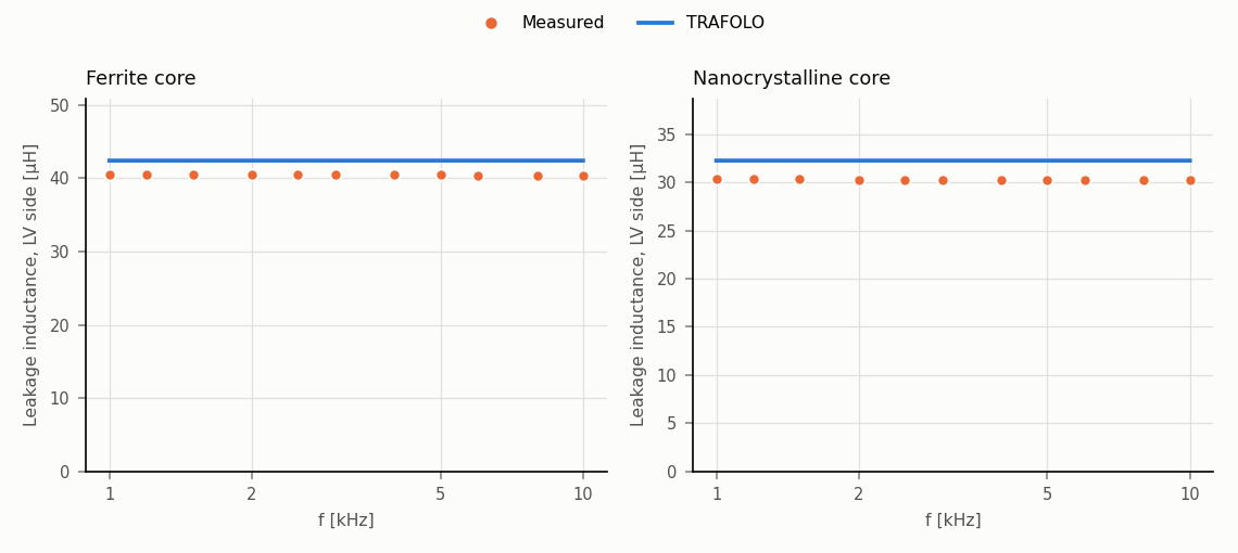
TRAFOLO computes the leakage inductance of two 50 kW medium-frequency transformers within 5 to 7 % of the measured value, at every frequency from 1 to 10 kHz.
- Result: ferrite core 42.4 µH against 40.4 µH measured (+4.9 %), nanocrystalline core 32.3 µH against 30.2 µH (+6.7 %).
- Source: M. Eslamian, M. Kharezy, T. Thiringer, "An Accurate Analytical Method for Leakage Inductance Calculation of Shell-Type Transformers With Rectangular Windings", IEEE Access 9 (2021), pp. 72647–72660, doi:10.1109/ACCESS.2021.3080242 (open access).
Case
| Part | Material in the model | Ferrite prototype [mm] | Nanocrystalline prototype [mm] |
|---|---|---|---|
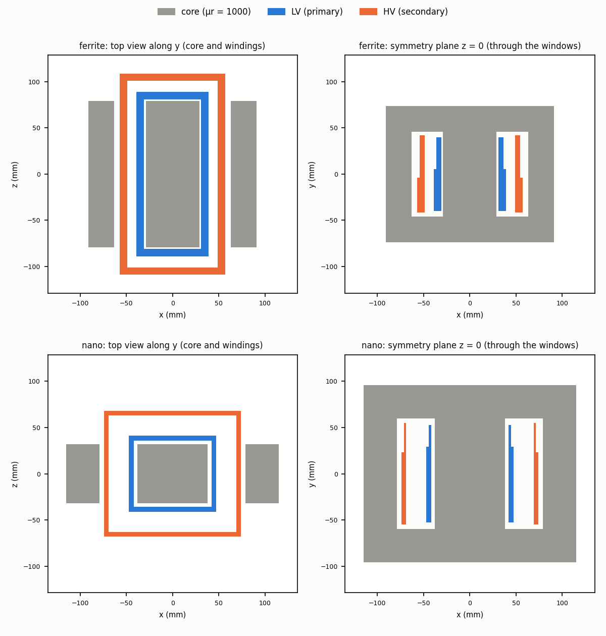
| Core, one block | ESL core mur1000: μr = 1000, σ = 0, no core loss | 182 × 148 × 158; windows 34 × 92; centre leg 58 | 230 × 192 × 64; windows 41 × 120; centre leg 76 |
| LV winding, primary | Copper, Stranded & Litz | 18 turns in 3 layers | 16 turns in 2 layers |
| HV winding, secondary | Copper, Stranded & Litz | 54 turns in 3 layers | 48 turns in 2 layers |
- Windings: litz of 181 strands × 0.2 mm in rectangular layers, placed as in the paper's Table 6.
- Excitation: LV at 54 A rms, the rated current, with the HV shorted; 11 frequencies from 1 to 10 kHz, as measured.
- Measured: with an LCR meter (Agilent E4980A) from the LV side, HV shorted.
- Air box: automatic, 3 × the part.
Results
| Prototype | Measured, mean 1–10 kHz [µH] | TRAFOLO [µH] | Difference [%] |
|---|---|---|---|
| Ferrite | 40.44 | 42.42 | +4.9 |
| Nanocrystalline | 30.24 | 32.26 | +6.7 |
Like the measurement, TRAFOLO's leakage inductance does not change with frequency.
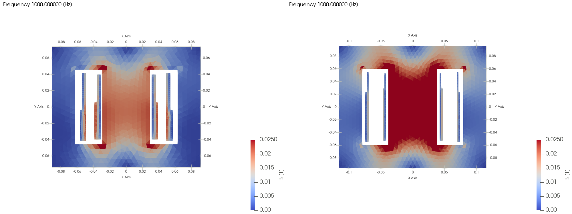
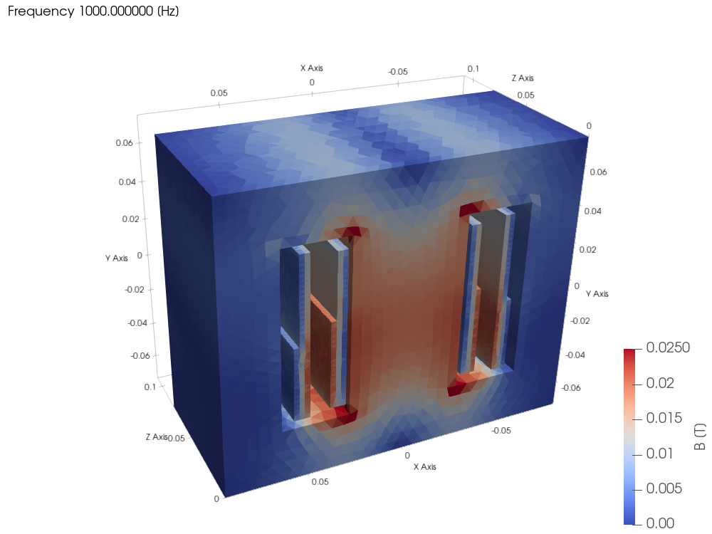
With the HV shorted, the flux runs between the two windings and closes through the core. Most of the energy is stored in the space between LV and HV, so their distance sets the leakage inductance.
TRAFOLO model
Built from STEP files of the paper's geometry (attached), in TRAFOLO 1.66.1beta.
| Tab | Setting |
|---|---|
| Setup | DOMAIN TYPE Symmetric: a half model, cut at the mid-depth plane. ELECTROMAGNETICS Inductance. |
| Geometry | CAD import of the core and the two windings, scale mm. |
| Materials | Core: ESL core mur1000 (μr = 1000, σ = 0). Windings: Copper. |
| Coil | Stranded & Litz; Turns per solid LV 18, HV 54 (nanocrystalline: 16, 48). |
| ElMag | Secondary Winding on: LV on the primary with current excitation, HV on the secondary with Urms [V] 0, a short circuit. |
| Waveform | Inductance Sweep, SWEEP BY Frequency: 11 frequencies from 1 to 10 kHz; primary 54 A rms. |
| Mesh | Max Element Edge Size: windings 1.5 mm, core 4 mm, air 20 mm; 670 000 to 770 000 elements. |
| Solve | Linear Solver MUMPS on 16 cores: the 11 frequencies in 15 to 16 minutes. |
Checks
- Mesh: a mesh with a third of the elements solves the 11 frequencies in 3 to 4 minutes and gives the same inductance within 0.6 %.
- Air box: doubling the automatic air box changes the inductance by 0.2 % (ferrite) and 0.7 % (nanocrystalline).
All runs
| Run | Prototype | Mesh: windings / core / air [mm] | Air box, x and y [mm] | Elements | Mesh / solve time [s] | L [µH] | vs measured [%] | Note |
|---|---|---|---|---|---|---|---|---|
| R0 | Ferrite | 2.5 / 6 / 30 | ±326.7 | 237 988 | 52 / 223 | 42.25 | +4.5 | First run |
| R0 | Nanocrystalline | 2.5 / 6 / 30 | ±345 | 223 298 | 47 / 183 | 32.06 | +6.0 | First run |
| R1 | Ferrite | 1.5 / 4 / 20 | ±326.7 | 668 771 | 174 / 965 | 42.42 | +4.9 | Reference run |
| R1 | Nanocrystalline | 1.5 / 4 / 20 | ±345 | 765 415 | 182 / 882 | 32.26 | +6.7 | Reference run |
| R2 | Ferrite | 2.5 / 6 / 30 | ±653.4 | 316 099 | 82 / 250 | 42.33 | +4.7 | Air box doubled |
| R2 | Nanocrystalline | 2.5 / 6 / 30 | ±690 | 368 715 | 92 / 276 | 32.30 | +6.8 | Air box doubled |
Each run solves the 11 frequencies on 16 cores; the half model reaches in z from 0 to the x value of the air box.
Limits
- Windings as blocks: each winding is one stepped block with uniform current density, as in the paper's own FEM model.
- Core as one block: the 2 mm (ferrite) and 4 mm (nanocrystalline) gaps between the core pieces are left out; the core grades are not stated, so μr = 1000.
- Surroundings: bobbins, heatsinks and mounting plates are not modelled.
- Low frequency: no eddy currents in the core or the litz, so the model gives the flat low-frequency leakage inductance.
Related
- Parasitic Extraction: leakage inductance and the other elements of the equivalent circuit
- Inductance (frequency and excitation sweeps)e
- Setup: the Symmetric domain